
FarmMind Tutorials
Mapping Irrigation Networks
FarmMind has an extensive irrigation network mapping system that you can use to organize or plan out an irrigation system. To map out or see an irrigation system, click 'See/Edit Map' on the irrigation card. You can also map out the system whenever you first create an irrigation system.
Irrigation Networks
In the FarmMind irrigation system editor, there are a couple of different components:
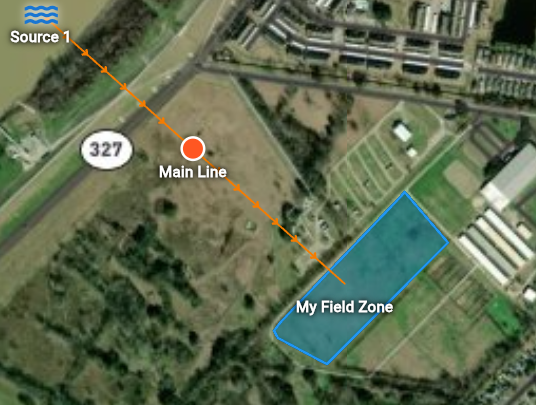
- Sources: These are your water/intake sources that distribute fluid to your fields. Common examples include wells, lakes, reservoirs, and ponds.
- Irrigation Loads: These are consumers of water/fluids, including center pivots, irrigation zones, or sprinklers.
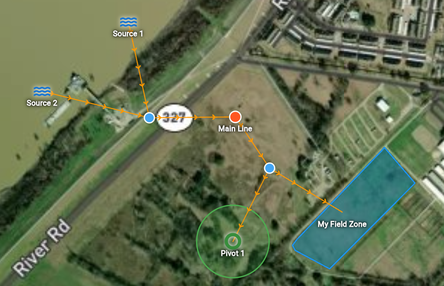
- Pipes: Pipes connect your Sources to your Loads (Consumers). A single pipe system can connect multiple sources and multiple loads via a shared 'main line' or 'manifold'.
- Valves: Valves can be placed on a pipe network and can disrupt the flow of fluid, and can be toggled on or off.
Adding Elements
You can add elements by clicking the add button on the top if on mobile or on the side panel if on desktop. Whenever you press a water source, input the source name, type, and optionally Maximum Gallons Per Minute (GPM) for the source. Then, press either place on map or place multiple to add it to the map.
Next, add an irrigation load. For this tutorial, we will assume that you chose an irrigation zone. If you did it this way, you can either select a field as the zone itself or you can manually draw the zone as a polygon. Once you have added your loads, it's time to connect them all with a pipe.
Irrigation Pipes
Click on 'Add pipes' and select the sources and loads that the pipe system will be connecting. Add other metadata as you please and click done. Congratulations, you made your first pipe network!
Above, you'll see all of the valves that exist in your pipe networks. You can toggle them on and off to restrict the flow of water. You can also add more valves to the irrigation network by pressing the valve element and selecting a place on the network.
You can add 'Junctions' to the network if you'd like to move where the lines go. Junctions can also connect one or more sources if on the source side or one or more loads if on the load side. To create a junction node, hover or click on one of the lines and then drag the junction to where you want it to be. Click on the new junction node and either add a new source or load to that junction. Junctions also act as valves.
Element Statuses
You are able to see whether or not each source and load is contributing or absorbing, as well as the total GPM required to supply the current active loads.